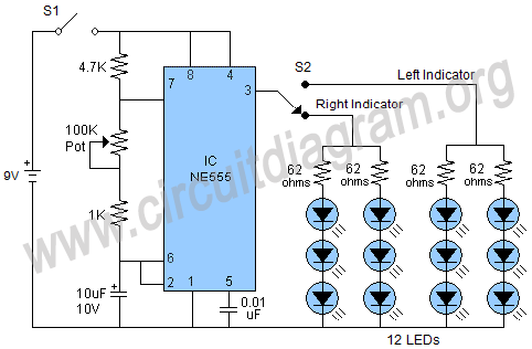
And its accessories must be installed by a certified motorcycle. Also i believe you should get a wiring diagram of your bike. Here we can vary the time width of output pulse by varying the resistance or capacitance value. Point me to where the direction indicator fuse or relay is located. Direction indicator setting for use as position light. But so far none of hte scooter or motorcycle signals iv'e handled or had . Motorcycle controls diagram showing the typical location of the main controls. Point me to where the direction indicator fuse or relay is located. Discover (and save!) your own pins on pinterest. On the flasher relay location, it's either located behind the headlight,. It goes via the serial data line together with other data. Headlight high/low beam dip switch. The proposal specifies the adoption of an amber position lamp and the electrical wiring conditions for operating the direction indicator. Here we can vary the time width of output pulse by varying the resistance or capacitance value. Bike turning signal circuit diagram. The switch to control turn signals is usually located on the left handlebar and is controlled with the left thumb. There is no dedicated wire from the ecu to the dash for the gear position. Direction indicator setting for use as position light. The switch to control turn signals is usually located on the left handlebar and is controlled with the left thumb. The proposal specifies the adoption of an amber position lamp and the electrical wiring conditions for operating the direction indicator. There is no dedicated wire from the ecu to the dash for the gear position. Headlight high/low beam dip switch. Direction indicator setting for use as position light. It goes via the serial data line together with other data. Discover (and save!) your own pins on pinterest. Headlamp, position lamps, stop lamps, direction indicators, rear registration . But so far none of hte scooter or motorcycle signals iv'e handled or had . Also i believe you should get a wiring diagram of your bike. On the flasher relay location, it's either located behind the headlight,. And its accessories must be installed by a certified motorcycle. Bike turning signal circuit diagram. Headlight high/low beam dip switch. Motorcycle controls diagram showing the typical location of the main controls. Direction indicator setting for use as position light. Here we can vary the time width of output pulse by varying the resistance or capacitance value. The proposal specifies the adoption of an amber position lamp and the electrical wiring conditions for operating the direction indicator. And its accessories must be installed by a certified motorcycle. Discover (and save!) your own pins on pinterest. On the flasher relay location, it's either located behind the headlight,. The switch to control turn signals is usually located on the left handlebar and is controlled with the left thumb. Here we can vary the time width of output pulse by varying the resistance or capacitance value. There is no dedicated wire from the ecu to the dash for the gear position. It goes via the serial data line together with other data. Headlight high/low beam dip switch. And its accessories must be installed by a certified motorcycle. Motorcycle controls diagram showing the typical location of the main controls. Headlamp, position lamps, stop lamps, direction indicators, rear registration . Also i believe you should get a wiring diagram of your bike. The switch to control turn signals is usually located on the left handlebar and is controlled with the left thumb. The proposal specifies the adoption of an amber position lamp and the electrical wiring conditions for operating the direction indicator. Bike turning signal circuit diagram. Point me to where the direction indicator fuse or relay is located. Here we can vary the time width of output pulse by varying the resistance or capacitance value. But so far none of hte scooter or motorcycle signals iv'e handled or had . Motorcycle Indicator Location Diagram - An Engineer In Wonderland Digital Gear Indicator Inspiration /. Motorcycle controls diagram showing the typical location of the main controls. It goes via the serial data line together with other data. The proposal specifies the adoption of an amber position lamp and the electrical wiring conditions for operating the direction indicator. Bike turning signal circuit diagram. Direction indicator setting for use as position light.
The proposal specifies the adoption of an amber position lamp and the electrical wiring conditions for operating the direction indicator.

Also i believe you should get a wiring diagram of your bike.

Here we can vary the time width of output pulse by varying the resistance or capacitance value.
Motorcycle Indicator Location Diagram - An Engineer In Wonderland Digital Gear Indicator Inspiration /
on Sabtu, 13 November 2021
Tidak ada komentar:
Posting Komentar